It can be helpful for Design & Technology students to have an understanding of how to cut, drill, and shape metal. This article summarises basic metalworking methods and practical techniques.
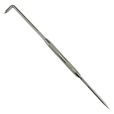
Metal can be marked out with a scriber, which scratches the surface (shown left) and a steel ruler or try square. A center punch can be used to mark hole locations. For curves, use calipers or carpenter dividers. (See more about these tools here.)
Casting (detailed information about casting needs to be studied by A2 students only, however AS students should have a basic understanding).
- Metal is heated in a crucible (a heat-resistant container with a pouring lip used to hold molten metal – often made from materials such as graphite), with the heat source commonly electric of gas-fired furnaces.
- Molten metal is poured into a mould (or injected in) and allowed to solidify into the desired shape. Examples:
- Sand casting (bit primitive, not high quality finish)
- Plaster of Paris casting (only works for non-ferrous metals)
- Die casting (a high-pressure manufacturing process that produces metal parts by injecting molten metal into a hardened steel mold, called a die – used for mass production of complex parts with high precision)
- Once cooled and solidified, the item is removed from the mould
Forging – Metal is heated and shaped through compressive forces using hammers or presses. The heat source is an electric, gas, or fuel-fired ‘forge’ which uses forced air from a bellows or a blower to raise the temperature high enough to make the metal malleable.
Rolling – Metal is passed through rollers to reduce thickness and create sheets, plates, or specific profiles.
Extrusion – Metal is pushed through a die opening to create continuous profiles with a fixed cross-section.
Drawing – Metal is pulled through a die to reduce its diameter and create wires or tubes.
Stamping/Pressing – Sheet metal is formed using dies and presses to create specific shapes through cutting, bending, or embossing.
Milling machine (can be manual or CNC). A machine used to shape metal by removing material with a rotating cutting tool. Unlike a drill, which only cuts downward along its axis, a milling cutter can cut on both its end and its sides, allowing it to produce flat surfaces, slots, grooves, steps, pockets, and complex profiles. The workpiece is clamped securely in a machine vice, bolted to a movable table, which can be moved precisely in three directions — left and right, forward and back, and up and down — so the operator (or computer) can control exactly where and how deeply the cutter removes material. Like a CNC router, but rotates are a slower speed and is more heavy duty, so better suited for cutting metal. Can take a wide variety of cutters in different shapes and sizes (just like you change the drill bit in a drill). Safety precautions when using a milling machine include wearing eye protection, tying back long hair, removing loose clothing and jewellery, never wearing gloves (which can catch in the rotating cutter), clamping the workpiece securely, using the correct cutter and spindle speed for the material, keeping hands well clear of the cutter while it is running, never clearing chips or swarf by hand while the machine is running, and always following the workshop’s lockout procedures before changing cutters or making adjustments.
Bending – Metal is clamped in a vice and bent manually, or heated for thicker parts and then bent, creating angles or curves.

Folding bars can be used to hold and clamp metal to aid bending. (Image sourced from D&T Online).
A former can also be used to bend multiple pieces into similar angles or shapes.
An anvil is a heavy, solid block of metal (traditionally iron or steel) used as a work surface for shaping metal. It has a flat top where you hammer or bend metal, and usually a horn (a curved, tapered end) for forming curves and rounded shapes. School Design & Technology workshops sometimes have a small bench anvil mounted on a sturdy base.
Spinning – A flat metal disc is spun very fast and pressed against a shaped mold to make a round/circular part like a bowl or cylinder (can sometimes be heated slightly to bend more easily, but the shaping is applied by pressure, not with the metal in molten form).
Powder Metallurgy – fine metal powder is pressed into a mould under high pressure to form a shape, then heated (but not melted) so the powder particles bond together into a solid part.
Centre lathe – as with using a wood lathe, metal can also be turned, making cylindrical or conical objects with parallel or tapered sides.
- Metal lathes are known as ‘centre lathes’ (heavier and more robust than wood lathes)
- Rather than being screwed to a face plate, the piece is held in a chuck (like how a drill bit is held by a drill) on the headstock spindle.
- At the other end is the tailstock which is used to hold any tools needed to centrally drill or lathe the centre. The inside of the tailstock barrel has a gently tapering cone shape inside (called a morse taper) — wider at the open end and narrower at the back. Drill chucks (holding small drill bits), large drill bits on their own, or reamers (a precision cutting tool used to finish a hole that has already been drilled, bringing it to an exact diameter with a smooth internal surface), and any other tools designed to be held this way can have a matching tapered shank at their back end, which can be wedged into the tailstock, held in place by friction. Large drill bits and reamers designed for lathes have a tapered end to slot into the morse taper without a chuck needed. This holds the tool dead-centre so that it spins in the middle. Alternatively, if lathing a long bar, the end of the bar can also be supported centrally inside the taper.
- The tailstock barrel can be wound in and out using the handwheel, bringing the tool toward the workpiece as the lathe spins.
- Metal turning tools (rather than chisels) are clamped to a tool post on the middle / side (not hand-held as with a wood lathe).
- Spins at different speeds to suit different materials (harder/tougher materials like stainless steel require slower speeds; softer materials like aluminium require higher speeds). Size of task may also require change of speed.
Drilling
There are special drill bits designed for use with various metals (obviously the drill bit has to be a stronger metal than the one being drilled)!
Chain drilling

Engineering Files
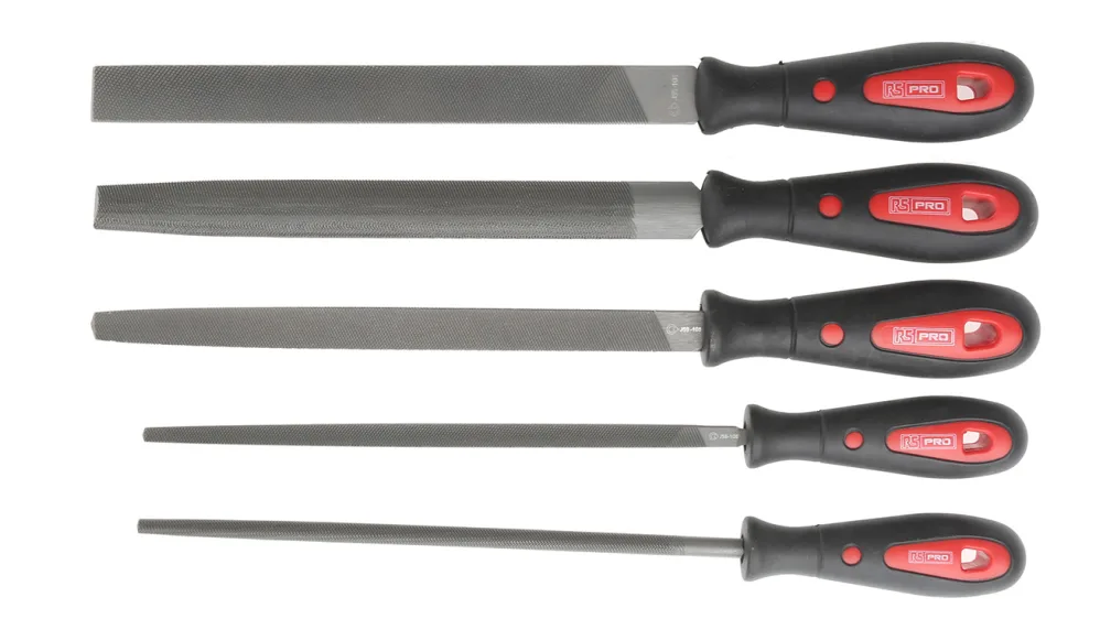
Engineer’s files are used for shaping, smoothing, and finishing metal, i.e:
- Deburring sharp edges after cutting
- Removing small amounts of metal to adjust fit
- Cleaning up rough edges or surfaces
Wet and Dry Sandpaper
- A special type of sandpaper that can be used either dry or wet
- Comes in a range of grit (rough through to smooth)
- Good for smoothing and polishing, as well as removing rust or paint from metal surfaces
- Often used wet to stop the sandpaper clogging
Emery paper
- Dark sandpaper for smoothing and finishing metal surfaces (used almost exclusively for metal, but can also be used on some plastics and other hard materials)
- Often uses a cloth backing paper rather than paper which makes it more flexible and able to withstand the heat and pressure of working with metal
- Comes in a range of grit like normal sandpaper, but the fine grades are much finer than sandpaper
- Like sandpaper, can be wrapped around a file or flat block of wood to achieve flat surfaces
- Can also be used with oil for lubrication and to prevent clogging
Manual cutting with hack saw
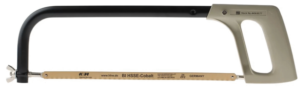
Normal saws cannot cut metal (the teeth on the blade break or get blunt) – instead a hacksaw is used.
Abrafile hacksaw blade

A straight round blade held in a hacksaw frame, which allows you to cut curves in metal (like a coping saw blade for metal).
Tin snips

Very thin sheets of metal can be cut with tin snips (basically extra tough / durable scissors for metal – normal scissors get blunt if you use them to cut metal)!
Sheet metal guillotine (metal shearing machine)
Has a heavy blade that comes down to cut through sheet metal (like a paper guillotine but more heavy duty). Can be hand-operated via a lever, foot-operated or an industrial hydraulic guillotine, depending on the thickness and frequency of cuts needed.
Grinder
Has an abrasive wheel or belt that removes small amounts of material to achieve precise dimensions, smooth surfaces, or sharp edges. It’s typically used as a finishing process after other forming operations, but a grinder can also be used with a cutting disk to cut through metal (common method for cutting sheet steel in a school workshop). You clamp the sheet, mark your cut line, and run the cutting disc along it. Less precise than a guillotine and leaves a rougher edge (which you’d then clean up with a file or grinding disc).
How to cut thread (enabling a metal part to screw in)
Threading die
Cuts thread on rods / bars etc
- Secure bar in a vice ensuring it is clamped tightly
- Use a file to chamfer the end (remove the sharp corner/edges) to help the rod go through the threading die
- Select a threading die (a circular cutting tool with internal cutting teeth) of the right diameter i.e. M8
- Place the die in a die stock / die holder(a handle that holds the die)
- Apply lubricant (cutting compound) to reduce friction and heat
- Turn the die stock clockwise to cut the thread (reverse occasionally as needed)
- Continue until desired thread length is achieved
- Be careful of swarf (metal shavings) as they are sharp and can cut fingers / go into eyes
Threading tap
Cuts internal thread in holes
- Secure item in a vice ensuring it is clamped tightly
- Drill a pilot hole of the correct diameter for the tap size (e.g. for M8 thread, drill a 6.8mm hole)
- Use a countersink bit to chamfer the hole entrance to help guide the tap in
- Select a tap of the right size/thread pitch (e.g. M8) – a tap is made of hardened steel so it cuts into softer metals
- Insert the tap into a tap wrench (the handle that holds the tap)
- Apply lubricant (cutting oil) to reduce friction and heat
- Keep the tap perpendicular to the surface (this is critical to avoid breaking the tap)
- Turn the tap wrench clockwise to cut the thread, reversing occasionally to break the swarf/chips
- When done, remove the tap by turning it anticlockwise
- Be careful of swarf (metal shavings) as they are sharp and can cut fingers / go into eyes
Note: Most laser cutters used in a school setting cannot cut metal, however some industrial high-powered ones can.
Sample examination questions (AS Design & Technology)


Examiner comment: The few candidates that answered this question often demonstrated an understanding of what part X was but did not always justify their answers.

Examiner comment: Most candidates had a basic understanding of why centre lathes have a range of speeds available, but candidates did not always extend their answers or give many examples.


Examiner comment:
(i) There was a significant amount of detail included in lots of responses with cutting out undertaken with chain drilling or a milling machine. Tools, equipment, and processes were generally well covered as were safety precautions.
Note: A milling machine would be an excellent way to cut a slot like the one in the sliding bevel blade. A cutting piece of the correct diameter would be fitted into the milling machine, the workpiece clamped securely in a machine vice, and the cutter plunged into the metal and traversed along the length of the slot — producing straight, parallel sides and smoothly rounded ends in a single operation, with a much cleaner and more accurate result than chain drilling.
(ii) A very well answered question with good understanding of how the bevel could be cut out and finished. Tools, equipment, and processes were generally well covered as were safety precautions.


Examiner comment:
(i) There was a significant amount of detail included in lots of responses with the use of heat and a jig to bend the metal being very well understood. However, the hole was often not drilled or threaded in Part A.
(ii) This was a very well answered question with good understanding of the use of a die stock to thread the bar. Tools, equipment, and processes were generally well covered.


Examiner comment: Candidates found this question challenging. The tools required were occasionally named but with very little detail on how to use them.


Examiner comments: There were many good answers clearly detailed both cutting and folding the material with the process of gaining accurate corners generally understood. Many candidates used technical terms for the tools and equipment that were being used. Safety precautions were not always included.


Examiner comment: There were some clear explanations of either forging or casting metal, depending on the choice of process. Safety precautions were not always included.


Examiner comment: Candidates gave a wide variety of answers to this question. Detailed answers included the use of a centre lathe or sand casting to produce the different sized brass weights.


Examiner comment: Candidates found it challenging to explain how to make the handle component. However, there were some clear explanations of marking out and cutting out the bracket based on traditional methods of fabrication. Safety precautions were not always included or were generic.
Teacher comment: The winding mechanism is essentially a crank handle attached to a shaft that passes through a bracket attached to the upright support.
In a school workshop, the shaft and crank handle could be made from a straight length of mild steel rod cut to length with a hacksaw (secure rod in bench vice, wear safety glasses, deburr cut ends with a file), and bend to form the crank handle. (Mark two bend points, clamp in a vice, and use a hammer to create a 90° bend. Reposition and repeat for the second bend.) A short piece of rubber tube or PVC tape could be slipped over or taped to the handle to provide grip.
The supporting bracket could be made with a thin mild steel bar with a threaded end. Cut to length (mark length, hold in vice, cut with hacksaw, file edges smooth), drilled with a pillar drill (clamp workpiece securely, use correct size bit slightly larger than the rod, safety glasses, hair tied back). While still flat, cut two clearance holes at either end for the shaft (mark out, pillar drill, clamp securely, hair tied up) and a screw hole to secure to the upright. Bend the bar into shape using a bench vice and hammer to wrap around the upright. Then screw to the upright to hold it in place.
Insert the shaft of the crank handle, and secure in position with a nut and washer on threaded end.


Examiner comment: Candidates were generally able to explain how to cut an M8 external thread on Part A with technical terms for tools and equipment accurately communicated.


Examiner comment: Stronger answers clearly described drilling the hole and tapping out with the use of lubricant. Many candidates used technical terms for the tools and equipment used. Safety precautions were not always included. Some candidates misunderstood the question and explained how to cut a thread
on part B with a die stock.


Examiner comment: Candidates gave a variety of different responses for making one aluminium pulley wheel. The most popular correct responses were sand casting or the use of a laser cutter to cut out three disks which were then connected together


Examiner comment: Candidates found it challenging to explain how to make part A. Very few candidates were able to communicate in detail how the lathe, with both parallel and taper turning, could be used. Safety precautions were not always included or were generic.


Examiner comment: Stronger answers detailed marking out, cutting out and folding of the top. Most candidates used technical terms for the tools and equipment used. Safety precautions were not always included. However, some candidates gave die casting as a process, which was incorrect.

Amiria has a Bachelor of Architectural Studies, Bachelor of Architecture (First Class Honours) and a Graduate Diploma of Teaching. She is a CIE Accredited Art & Design and Design & Technology Coursework Assessor. Amiria now teaches Art, Design & Technology at ACG Parnell College.