High school Design & Technology students are often asked to identify and name different features of control systems, such as input devices, processing elements, output devices, feedback, and amplification. This article summarises this content and helps students prepare for examination questions on this topic.
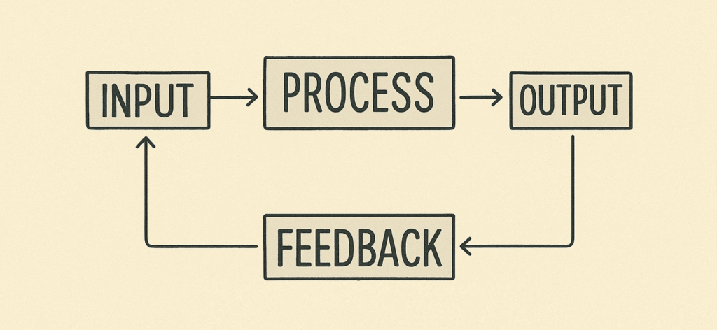
Products that use electricity or other forms of energy to carry out a particular task can be thought of as a ‘control system‘ (in other words, a system where all the components work together – or are controlled in some way – to carry out a particular function). Larger systems made of several products working together can also be viewed in this way. Thinking about separate components as a ‘system’ is particularly common in electrical, computing, or mechanical products.
What is ‘systems thinking’ in product design?
- A simple way of thinking about complex systems
- Focuses on the interconnectedness of components (or products), rather than just an isolated element on its own – and how these interact and influence the whole system
- It categorises components into separate blocks: input, processing, output, feedback and amplification
What are ‘input devices’ or components?
- Input devices put information into a system.
- This information is detected, measured, or received from the environment or user.
- The input device converts this information into a signal (often an electronic signal) that is used in the system.
Input devices allow systems to understand changes in the environment around them. It is a device used to input data or information.
Bitesize BBC
Examples of ‘input’ devices or components
- Switches, knobs, buttons (typically activated by a human user)
- LDR – Light Dependent Resistor – light sensor activated by light
- PIR – Passive Infrared – motion sensor activated by changes in heat patterns, detecting the motion of a warm body), such as in burglar alarms or motion activated lights
- Thermistors (temperature sensors)
- Microphones (detects sound)
- Pressure sensors
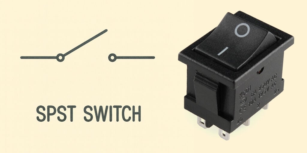
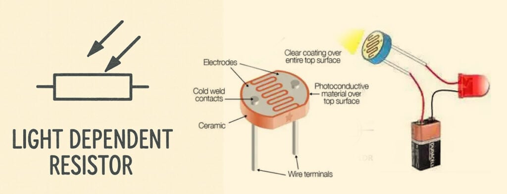
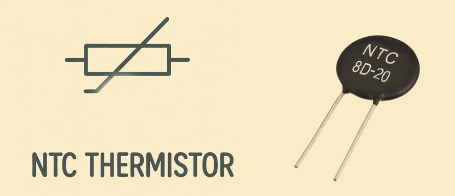
Whole devices can also be considered ‘input devices’ such as:
- Digital cameras (converts light into a digital file)
- Mouse and keyboard (convert movement / pushing buttons into a digital signals)
- Graphics tablet (converts pressure on surface into a digital signal)
- Scanners
What are ‘processing’ components?
- These are things that change the incoming signals within the system into something different
- Change one form of energy or information into another
- Can involve algorithmic decision-making, computations, or sequences of programmed rules, run by software
- Raw inputs are transformed into something else, leading to the desired output
Examples of ‘processing’ components
- Digital software (i.e. Techsoft Design, or Adobe Photoshop)
- Microprocessors (a single chip in a digital product that processes data and performs calculations at high speed – typically found in devices that need to run many different apps or software, like computers or smartphones)
- Microcontrollers (like a simpler, self-contained computer on a single chip – has a small processor plus built-in memory, perfect for controlling specific tasks in electronic products that do a specific automated task, like the wash cycle in a washing machine)
- Gears, levers or cams in a mechanical system are also a type of processing component and can transform motion
- Resistors, variable resistors, and potentiometers
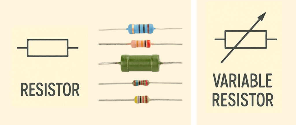
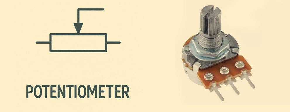
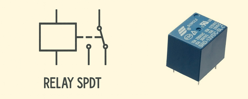
A chip (also called an integrated circuit or IC) is a tiny piece of silicon with thousands or millions of microscopic electronic components built into it, like a miniature circuit board with all its transistors, resistors, and connections etched onto the surface.
What are ‘output’ devices?
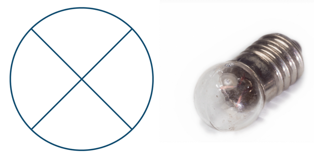
- These are the components that transform the processed signals back into real-world outputs, such as light, heat, sound, which come out of the system as the desired result
- Lightbulbs or LEDs (light emitting diodes)
- Buzzers
- Motors – convert electrical or chemical energy into motion / movement
- Electrical heaters – convert electricity into heat
- Speakers – convert electricity into sound waves
- Digital printers – convert digital signals into physical documents
- Laser cutters
- 3D printers

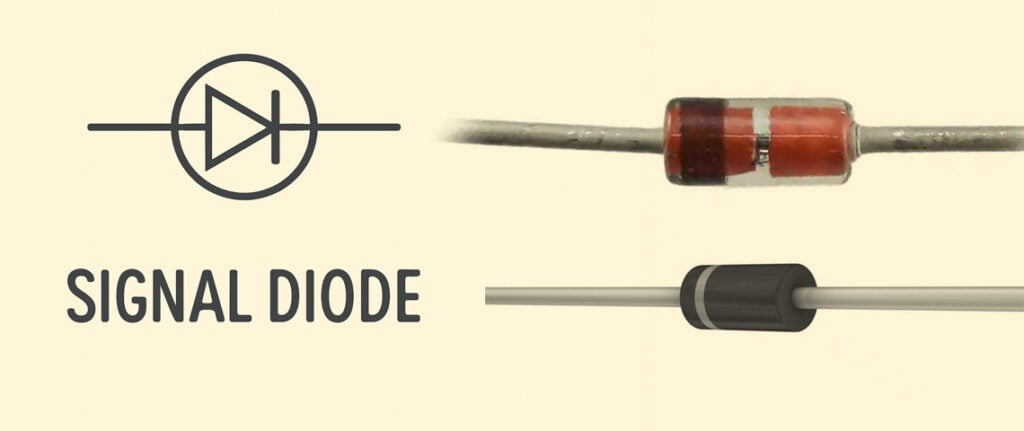
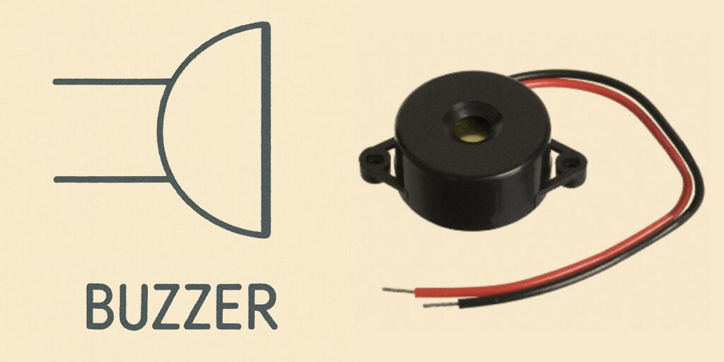
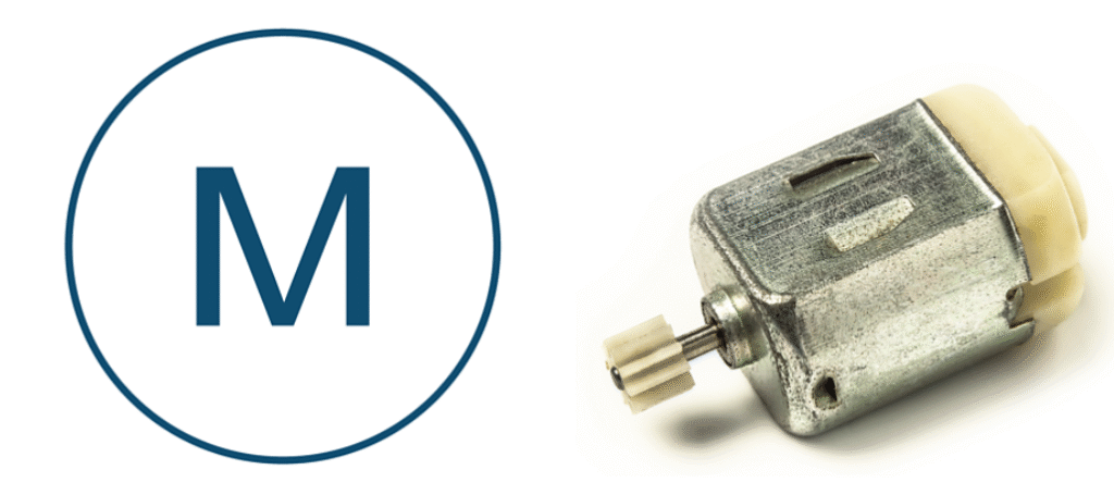
Examples of control systems
A simple example of a control system that relates to graphic products:
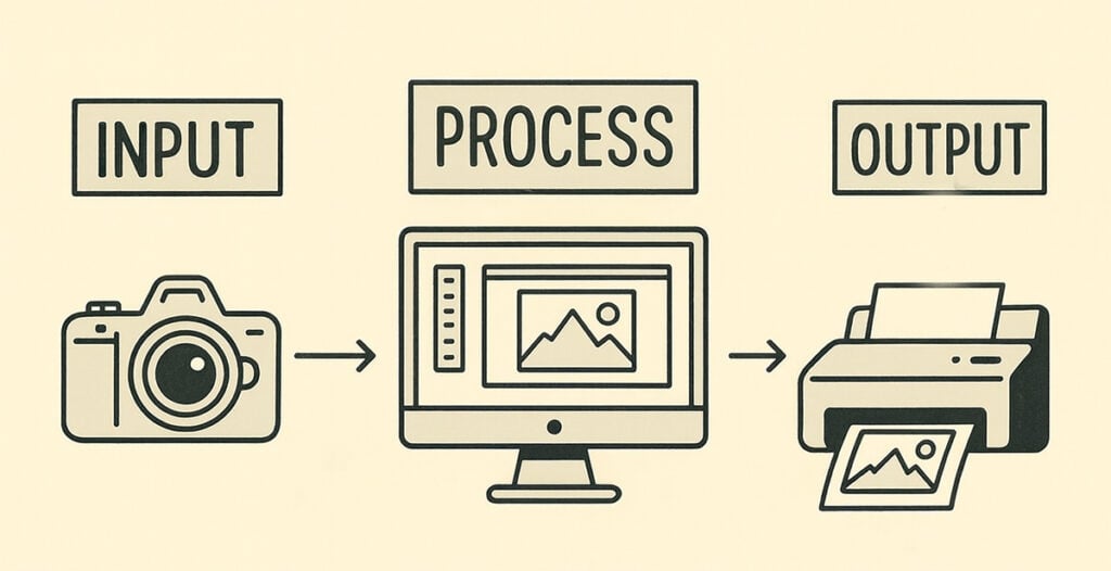
- Input: Digital camera captures light and converts it to digital image data
- Processing: Software (like Adobe Photoshop) manipulates that data – adjusting colors, cropping, applying filters, resizing, etc.
- Output: Printer converts the processed digital data into physical ink patterns on paper
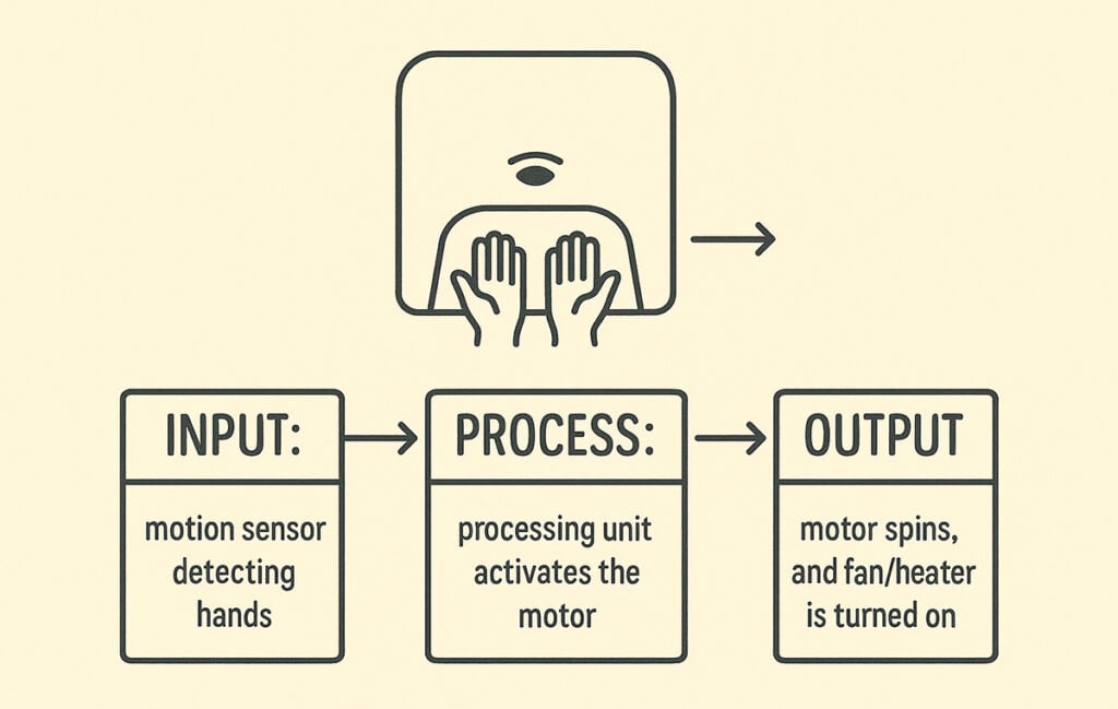
Single products can be represented as control systems too, such as this automatic hand dryer:
Or a bicycle:

- Input: pedaling force from the rider’s legs (as well as other inputs, such as turning steering wheel and squeezing brakes)
- Process: gears, chain, and sprockets transfer the pedalling force into rotational motion
- Output: wheels turn, propelling bike forward
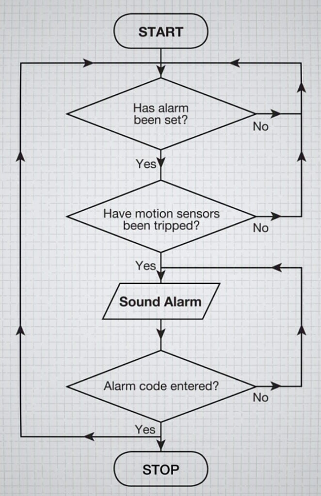
Note: When drawing flow charts, inputs and outputs are shown as parallelograms.
An example of a flow chart for an alarm system with the output ‘Sound Alarm’ drawn using the output symbol (source: BBC Bitesize).
Manual, semi-automatic and automatic control
- Manual control – a human operator reading inputs (like gauges or sensors) and deciding what actions to take.
- Semi-automatic control – combines human and machine input. For example, the system might gather and display feedback data (e.g., a digital thermometer), but the human still decides and initiates the response, like pressing a button to turn on a fan.
- Automatic control – the system handles everything on its own. A microcontroller continuously reads inputs, processes the data, and adjusts outputs (like temperature or motor speed) without any human intervention. It forms a closed-loop system, adjusting itself in real time based on feedback.
What is ‘feedback’ in system analysis and design?
- Feedback is the mechanism whereby output influences future behavior of the system
- Example: a thermostat might measure the temperature in the room, so it then knows whether to increase or decrease the temperature.
- The output becomes an input to adjust the future behavior of the system
- Feedback creates a loop in the system, allowing self-regulation and control
- This helps to minimise errors in the system, ensuring the system adapts to change
- Feedback can be positive (increasing certain behaviors or outputs) or negative (prompting corrective actions and/or reducing certain outputs)
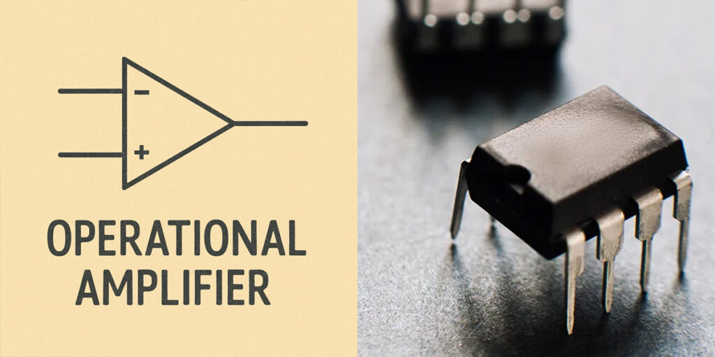
Amplification
In the context of system analysis and feedback systems, amplification refers to increasing the strength or magnitude of a signal – typically the output signal – based on input or feedback.

Why designers use basic control principles of input, process, output, feedback and amplification
- A concise way of thinking about complicated systems: allows designers to consider all aspects of a system and how they related, making planning, describing, and understanding the system easier
- Can makes it easier to troubleshoot errors as you can more rapidly identify which part of the system contains the error
- Assessing how different parts of a system work together helps create more intuitive products, ensuring various sensors (inputs) work harmoniously with display elements (outputs) to create a seamless user experience.
- Quality control: Monitoring input and output helps maintain consistent product performance. For example, a factory creating packaging might use automated sensors (input) to monitor product outcomes while feedback systems adjust mechanisms in response. Feedback allows designers to develop ‘responsive’ machines, with continuous monitoring of performance, with parts of system set to switch off if certain limits are reached, helping to avoid disastrous outcomes.
- Understanding control systems helps designers plan for product maintenance. For instance, monitoring systems in digital displays can provide feedback about component wear, enabling predictive maintenance schedules.
- Environmental adaptation: Control principles allow products to adapt to changing conditions, such as temperature or humidity changes.
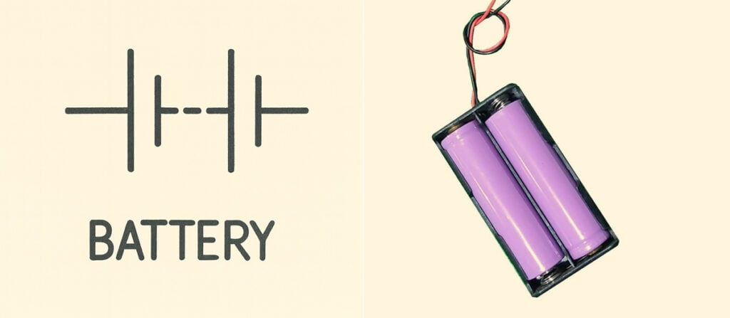
Components in an electronic system can represented as circuit diagrams. See the full list of common circuit symbols.

A capacitor is an electronic component that stores electrical energy temporarily in an electric field. It can be thought of as a tiny rechargeable battery that charges/discharges in milliseconds.
Stores small amounts of electricity to keep things running smoothly. When electricity is “jumpy” or “noisy,” capacitors make it calm and steady. They also help motors start and run. In almost all electrical products.
Sample exam questions (AS)
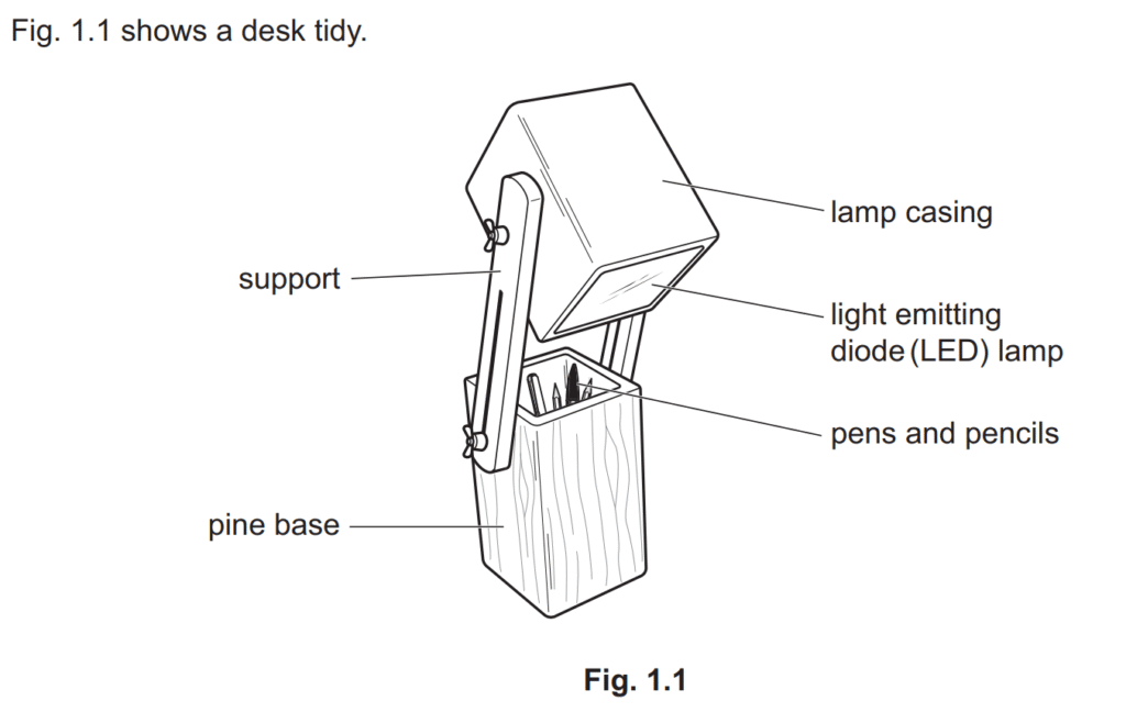


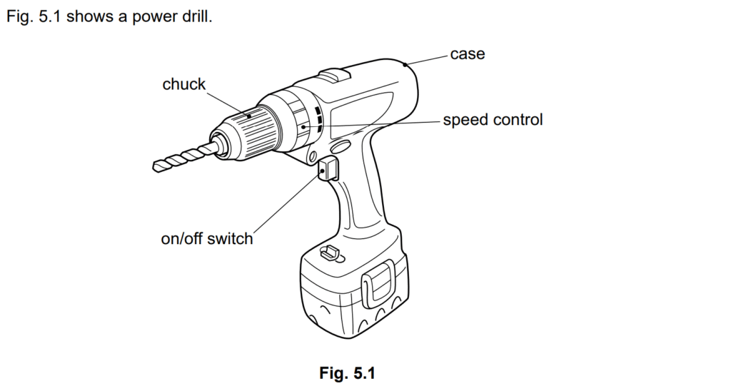

Electrical energy [1]

The rotary motion of the drill [1]

Explain how amplification is important to drill through different materials.
- Amplification is important because it enables the drill to have different speeds to get through different materials [1] with lower speeds for harder materials and faster speeds for softer materials [1]
Accept all valid responses.
- Amplification is important because it allows the speed of the motor/drill to be changed [1]; the speed must match the diameter of the drill bit or material being drilled [1]
- Amplification is important because it allows us to increase the speed of the drill [1] by controlling the flow of the current and/or the switching on/off of the drill/amount of pressure used on the switch to change the torque [1]

Name one component that can be used in the amplification.
Motor [1]
Accept all valid responses.
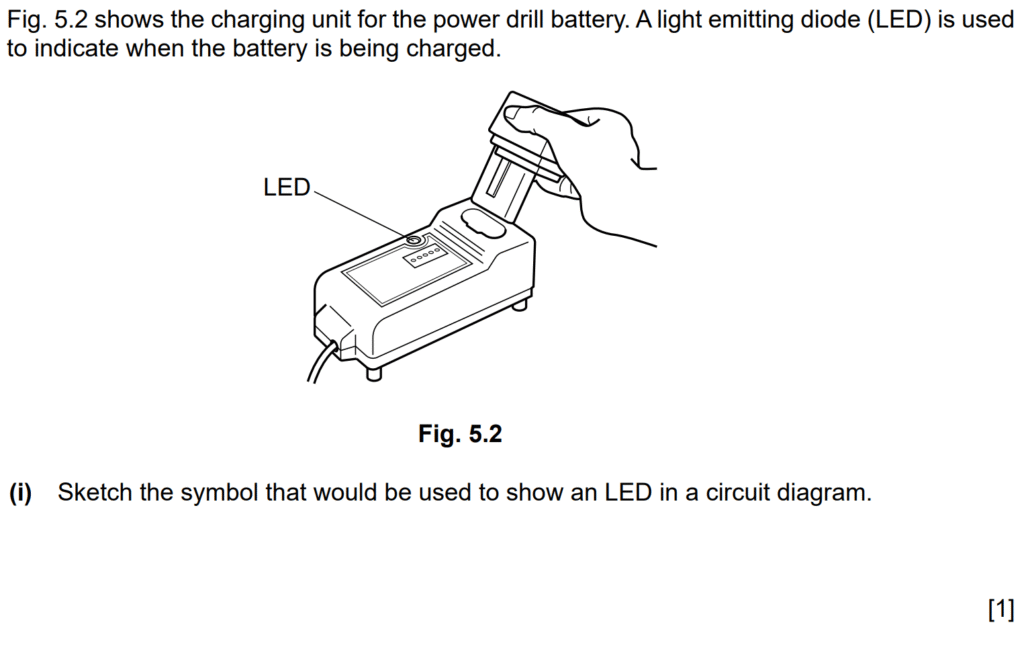
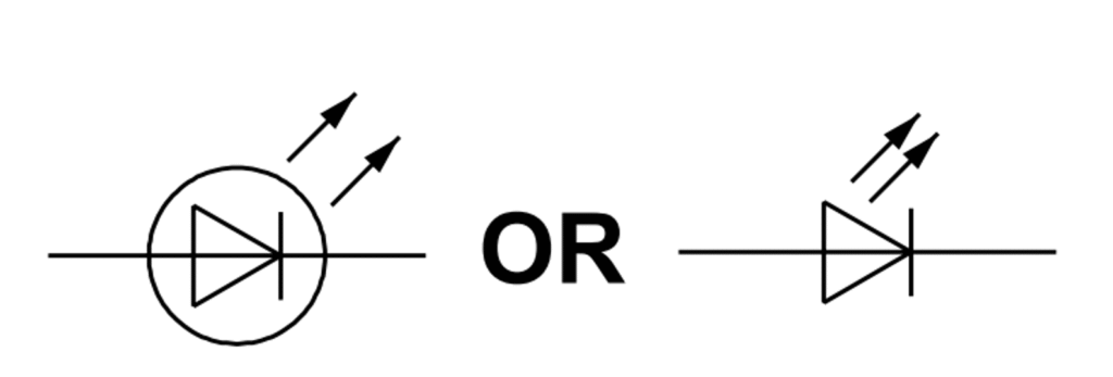

State one reason why an LED is suitable for indicating a battery is being charged.
Exemplar answers:
- Less likely to break than a bulb [1]
- Uses less electricity than a bulb [1]
- Available in a range of colours [1]
- Low cost compared with a bulb [1]
Accept all valid responses.
