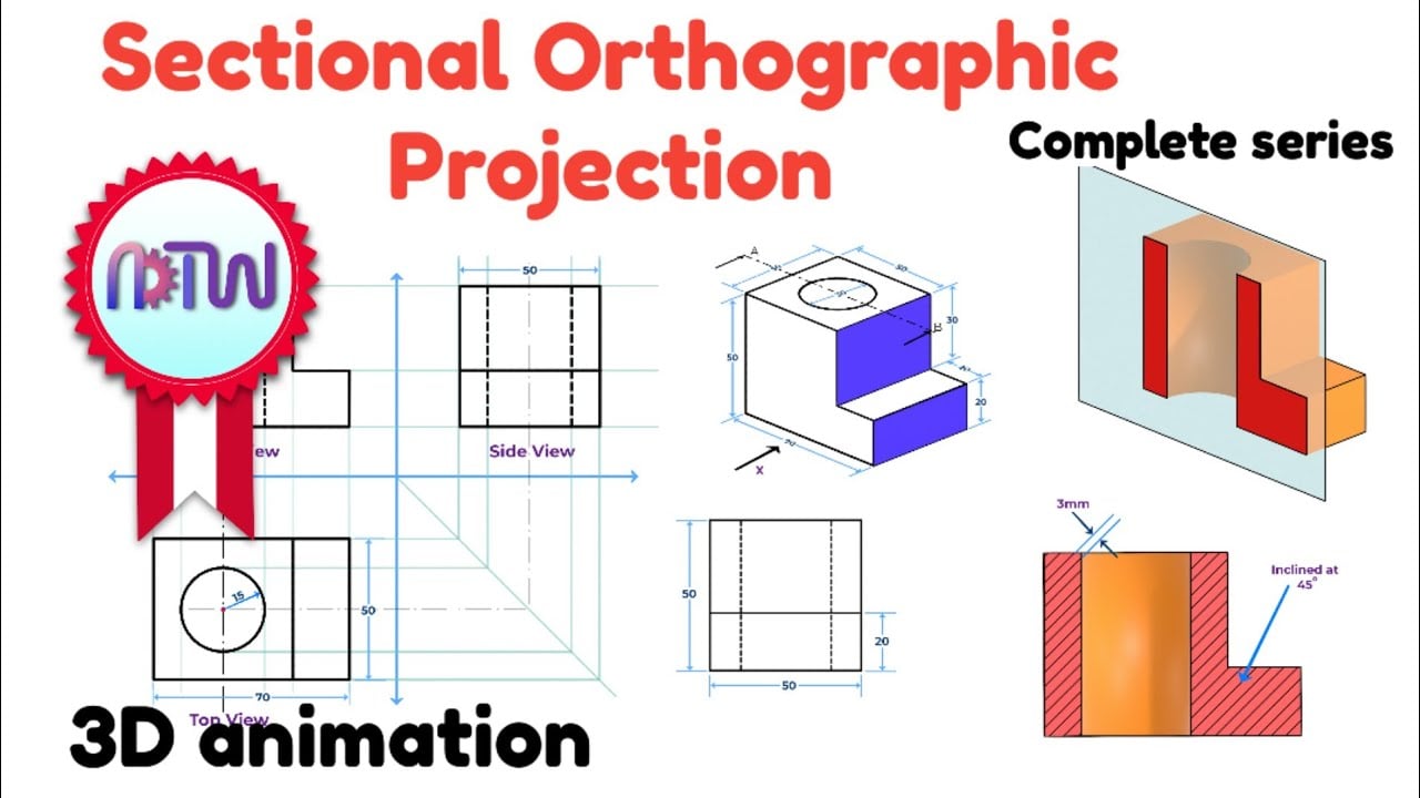
Sectional drawings show what an object looks like as if it had been cut open or sliced through.
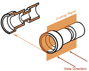
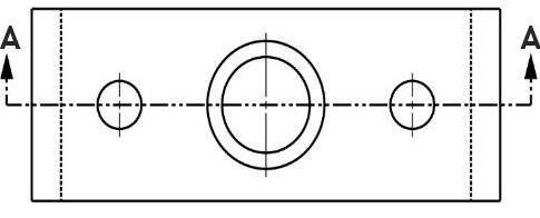
- A ‘section line’ or ‘cutting plane‘ is drawn to show where the item has been ‘cut’. The cutting plane is drawn as a long dash – short dash line. The line is typically thicker at each end, and thickened at any change of direction if the cutting plane is stepped (such as an offset section). The arrows show the direction the section is viewed from and are drawn perpendicular to the cutting plane, pointing in the direction the observer is looking at the cut surface.
- The purpose of a section is show the interior of an object and are useful for showing how things are put together or assembled
- An object is usually ‘cut’ in the place that shows the most internal detail
- Both the section line and the section are labelled with the same letters, i.e. Section ‘A-A’
- Cut surfaces have diagonal ‘hatching‘ (angled parallel lines) to show that they have been cut.
- Pins, dowels, bolts, nuts etc are not sectioned (because the purpose of a sectional drawing is usually to show where these items go)

Nut and bolt guidelines: In exams, which follow conventional British drawing standards, bolts are referred to like this: M10 × 45. The M means metric, the 10 means the outside/largest diameter of the thread is 10mm. The 45 refers to the length of the bolt shaft, measured from under the bolt head (unless a countersunk bolt, where length is measured overall, because the head sits flush within the material).
Hatching guidelines for cut surfaces
- Hatching lines should be parallel & evenly spaced (don’t measure – that would take way too long! – instead use the groove on the edge of your set square to rapidly produce evenly spaced lines)
- Lines can be on any angle (common to start with 45° lines) but must not be same angle as edge of object
- Hatching lines on different components should go in different angles
- Hatching lines should be thin and approximately 2-4mm apart
- Don’t hatch pins, dowels, bolts, nuts etc
- Very thin cut surfaces are coloured solid black (as they are too fiddly to hatch). For example, walls on a planometric sectional floor plan would just be coloured black.


- If hatching really large areas, hatching can only be partially drawn, near the edges

Half Sections
- Sections in which only half of the object is cut away
- Usually used when the object is symmetrical
- Allows both the external and internal view to be shown within one drawing

Part Sections
- These are used when only small areas need to be cut away in order to show important details
- The line where the part section ends is simply a thin wavy continuous line (as if part of the surface has been ‘torn’ away)

Revolved Sections
- Shows a cross section rotated so that it can be seen
- It is drawn in place on the normal view

Removed Sections
- Removed section are revolved sections that have been moved away from the main view

Offset sections
- The cutting plane can change directions and turn corners so that the most detail is shown (this is called an offset section)

Sample examination questions (IGCSE Paper 5)

Note: Please read the article about vacuum forming to learn about draft angles.

Examiner comment: Candidates were required to complete the sectional view of the ready meal tray to a scale of 1:2. Many candidates drew the tray to the correct depth but with the individual sections of inaccurate widths.
Note: As the cut surface is very thin, it is just represented by a very dark line – no hatching is used.

Amiria has a Bachelor of Architectural Studies, Bachelor of Architecture (First Class Honours) and a Graduate Diploma of Teaching. She is a CIE Accredited Art & Design and Design & Technology Coursework Assessor. Amiria now teaches Art, Design & Technology at ACG Parnell College.